

FreeCAD
About FreeCAD
FreeCAD builds 3D objects from dimensions you can change later. Draw a sketch, give its lines lengths and angles, pull it into a solid, then cut a hole and round the edges. Every step is kept in a history tree on the left. Go back to the first sketch, change a width from 40 to 45 millimetres, and the whole part rebuilds around the new number. That is parametric modelling, the method behind the commercial engineering programs, and this one offers it with the source code open and no account to sign into.
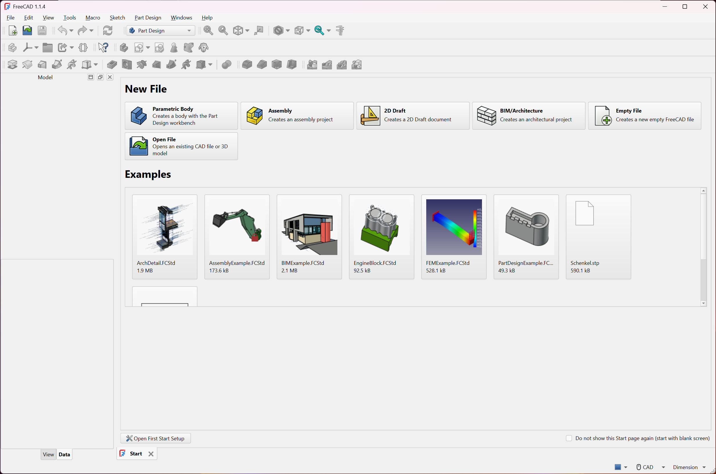
It is a large program, and it is organised in an unusual way. Tools live in workbenches, separate toolsets for sketching and solid modelling, assemblies and drawings, and the specialist work of simulation or architecture, and you switch between them as the job changes.
FreeCAD has also cleared the two hurdles that long kept serious users away. Its handling of the references between features no longer breaks models when an early sketch changes, at least in the core modelling tools, and an assembly workbench is now built in.
The learning curve remains steep, and the sections below explain the parts you will meet, in the order you meet them, and where the program still asks patience.
Workbenches, and why tools seem to be missing
The single most common FreeCAD beginner complaint is that a tool has vanished. It has not. It lives in another workbench. A dropdown, or a row of tabs in newer layouts, switches between them, and the toolbars change with each. The Sketcher draws constrained 2D profiles. Part Design turns them into a single solid body. Part works with primitive shapes and Boolean combinations. Draft handles 2D and general geometry editing. TechDraw makes drawings, and Assembly puts parts together.
Think of workbenches as rooms in a workshop rather than menus. You sketch at one bench, shape the part at the next and draw it up at a third, and the model travels with you. Most mechanical parts need only the Sketcher and Part Design, and learning those two first, before touching the rest, is the advice nearly every tutorial gives.
Sketches and constraints
Everything in FreeCAD starts in the Sketcher. You draw lines and arcs on a plane, then tie them down with constraints. A line is horizontal, two lines are equal, a hole sits 20 millimetres from an edge, an arc is tangent to a line. The sketch counts its degrees of freedom and turns green when it is fully constrained, which means its shape is defined entirely by the numbers you gave.
That green state matters. An under-constrained sketch can shift unexpectedly when you edit it later, and the later features built on it shift too. Constraints can refer to values in a spreadsheet, so a single table of key dimensions drives a whole model.
The Sketcher is the part of the program that rewards care most and punishes haste most, and it is where a beginner should spend the first evenings.
Part Design and the model tree
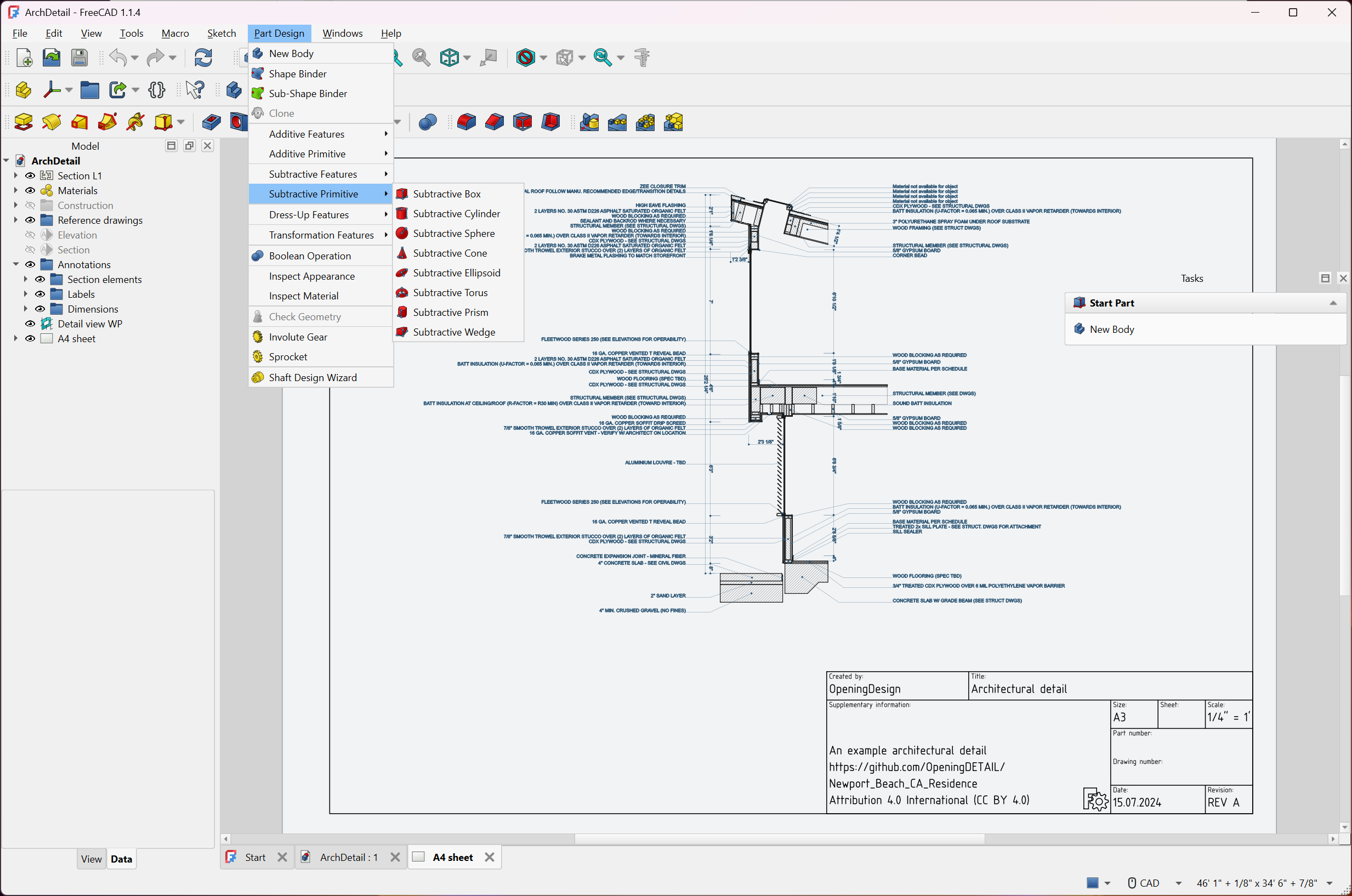
Part Design turns sketches into solid features. Pad extrudes a sketch, Pocket cuts it away, Revolution spins it around an axis, Loft and Sweep join profiles along a path, and Hole creates holes to standard sizes with counterbores and threads. Fillets and chamfers round and bevel edges. Patterns repeat a feature along a line or around a circle, or reflect it across a plane.
Each feature stacks in the tree under a Body, and the order is the recipe. Change a value anywhere and the features after it recalculate. A broken feature shows in red, with the reason in the report view. For a far simpler starting point aimed at hobbyists, Autodesk 123D Design teaches the push-and-pull basics before a move to full parametric work.
The naming fix, and what it means
The program long had a reputation for models that fell apart. The cause was topological naming. When an early sketch changed, the faces and edges of the solid were renumbered, and a sketch attached to “face 6” found itself on the wrong face or on nothing at all. Models exploded into errors after an innocent edit.
Current FreeCAD releases track those references through changes, so editing an early feature no longer scrambles the ones after it. The project is honest that the work is not finished everywhere. The fix covers the Sketcher and Part Design, which is where nearly all solid modelling happens, and other workbenches follow. Good habits still help.
Attach sketches to datum planes rather than to faces where you can, and keep the tree simple.
Assemblies
An assembly workbench now ships with FreeCAD. It combines separate parts into a product, connecting them with joints that fix parts or let them hinge and slide, and a solver positions everything according to those joints. Sub-assemblies can move internally while staying rigid within a larger assembly, so a cylinder can extend while its housing stays put.
It works, and for most hobby and small engineering assemblies it is enough. Reviewers who compare it with the mature commercial tools describe it as younger and less polished, with fewer joint types and less help when constraints conflict. Several community assembly add-ons remain available for those who prefer an older approach.
Drawings and the specialist workbenches
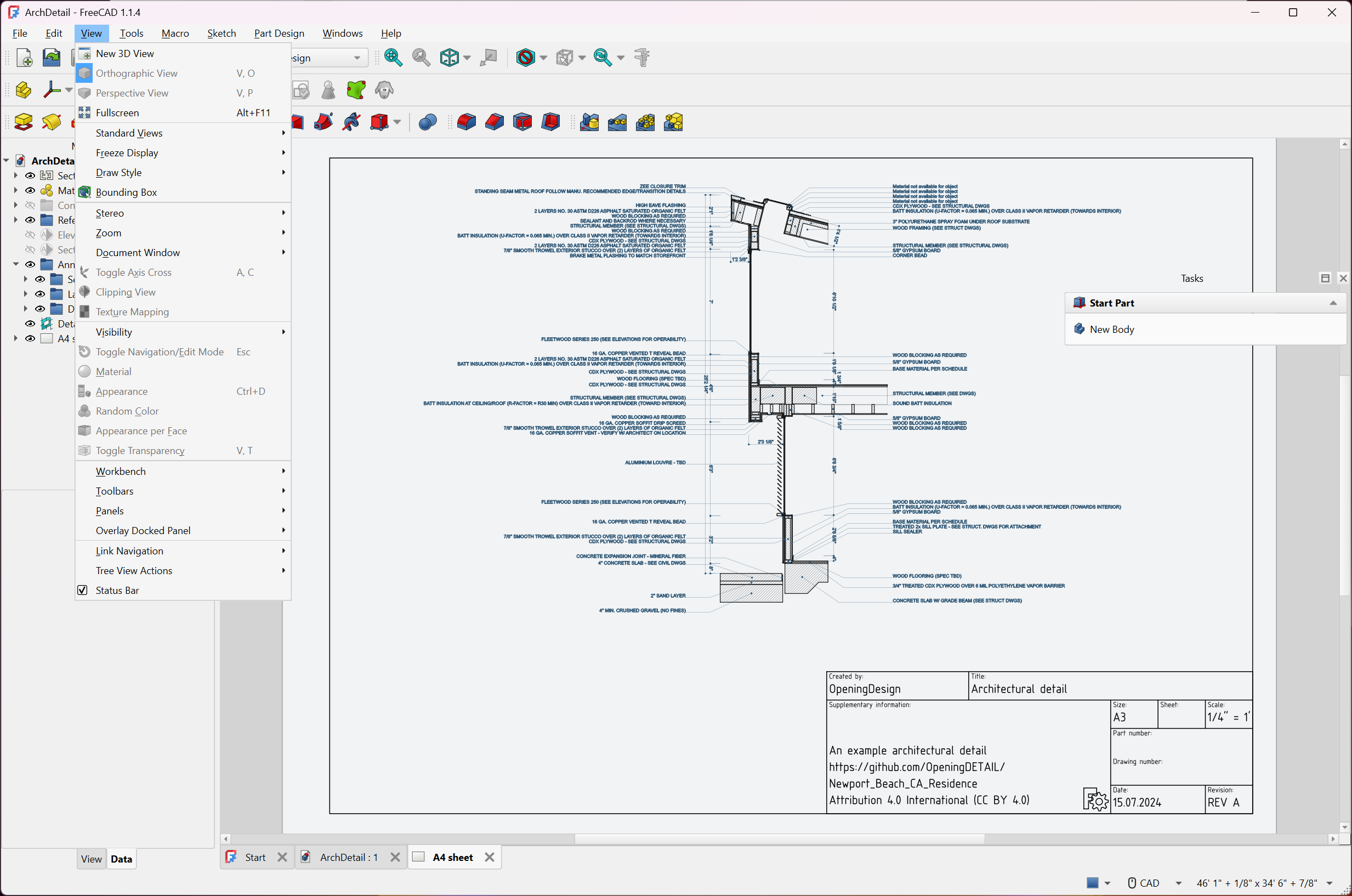
FreeCAD TechDraw produces technical drawings from the 3D model, with projected views and sections, plus dimensions and title blocks, and the drawings update when the model changes. They export to PDF, SVG and DXF. For editing 2D DWG drawings as such, DraftSight is the more natural tool.
Beyond that, the FEM workbench runs finite element analysis, the stress and deflection of a part under load, through external solvers. The CAM workbench generates toolpaths and G-code for milling machines and routers. BIM covers architectural design with walls and windows, and exchanges IFC files with other building software.
Each of these is a substantial program in its own right, and each adds its own learning curve.
Files and scripting
The native FreeCAD format keeps the full parametric history. For exchange, STEP and IGES carry solid geometry to and from commercial CAD, STL and OBJ go to 3D printing and rendering, and DXF and SVG handle 2D. A part exported as STL slices straight into Cura for printing.
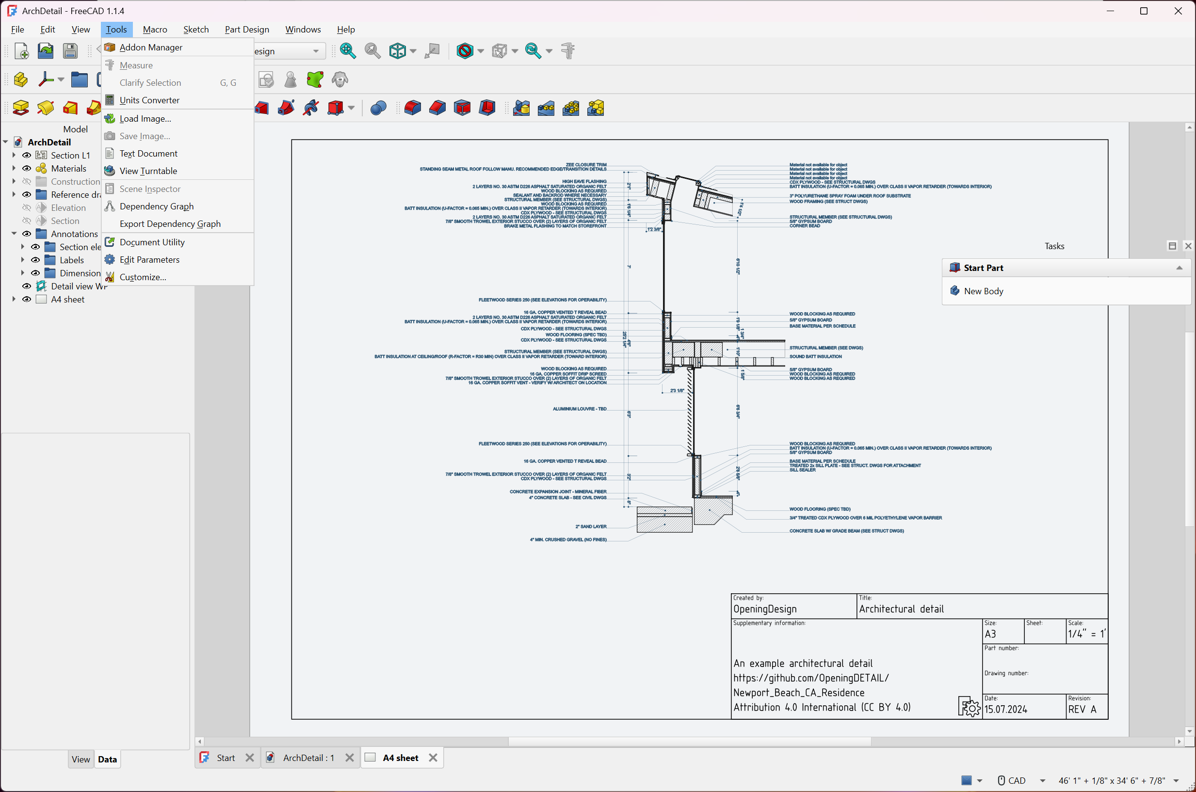
Everything in the program is reachable from Python. A console shows the code behind each action as you click, which is how many users learn the scripting interface, and macros automate repetitive work. An Addon Manager installs community workbenches and macros from inside the program, covering gears, fasteners, sheet metal and much more.
Where it asks patience
The FreeCAD learning curve is the honest headline. Reviewers suggest a few weeks of regular use before the parametric approach feels natural, and the workbench layout surprises everyone at first. The interface has been modernised but still shows its engineering roots. Error messages are technical. The assembly workbench is younger than its commercial rivals, and the naming fix does not yet reach every workbench.
For organic shapes and rendering rather than engineering parts, a full 3D modelling suite is the better fit. For mechanical parts and anything that must fit together to a measured dimension, this is a complete engineering toolset. The effort of learning it pays back the first time a design changes and the model simply follows.
Conclusion
FreeCAD suits makers and engineers, and students, who design mechanical parts and want a parametric modeller they can grow into, from a 3D-printed bracket to an assembly with technical drawings and a stress check. The Sketcher and Part Design form a solid core, and the specialist workbenches extend it further than most programs in the field.
It asks for time, and its newest pieces are still maturing. Learn the Sketcher until green feels normal, keep sketches attached to datum planes, and the program rewards the effort with models that change as easily as their numbers.
Pros & Cons
- Full parametric modelling with an editable history tree
- Constrained sketches that turn green when fully defined
- Reference tracking that keeps models intact when early features change
- Built-in assembly workbench with joints and moving sub-assemblies
- Technical drawings, finite element analysis, CAM toolpaths and BIM in one program
- STEP, IGES, STL, OBJ, DXF and IFC exchange, plus Python scripting and add-ons
- Steep learning curve, with tools spread across workbenches
- Assembly workbench is less mature than commercial alternatives
- The naming fix covers the core modelling tools, not every workbench
- Technical error messages and an interface that still feels engineering-first
Frequently asked questions
It is probably in another workbench. Switch workbench from the selector, and the toolbars change to that workbench's tools.
Much less than it did. Current releases track references through changes in the Sketcher and Part Design. Attaching sketches to datum planes rather than faces adds a further safety margin.
Yes. A built-in assembly workbench connects parts with several joint types, and community add-ons offer alternatives.
It exchanges solid geometry through STEP and IGES, which most commercial programs read and write. Native files from those programs are generally not opened directly.
Yes. Export the solid as STL or OBJ and open it in a slicer.
Yes, through Python. The console shows the code behind each action, and macros automate repeated tasks.


