

4nec2


 (20 votes, average: 3.55 out of 5)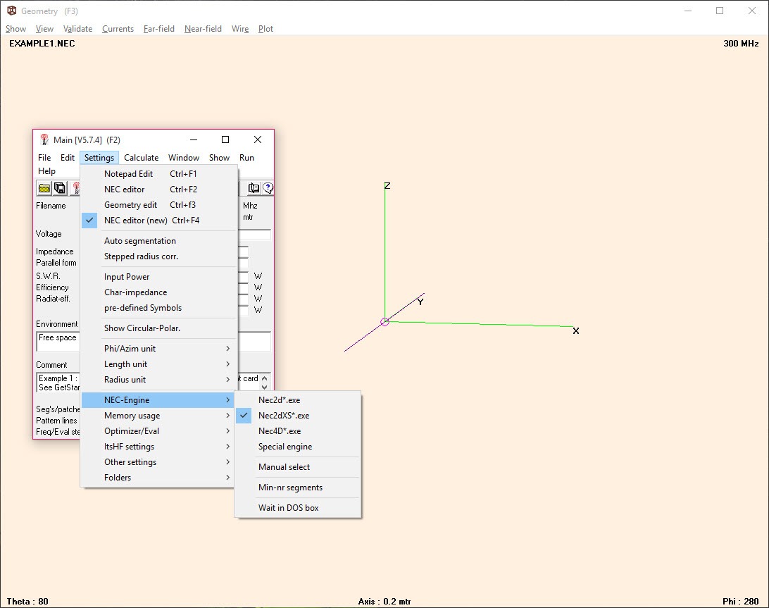
About 4nec2
Building an antenna and then measuring it is expensive in time and aluminium. Modelling it first costs an evening. 4nec2 puts a well-established calculation engine behind a graphical interface, so a design can be tested, adjusted, optimised before anybody cuts anything.
The model is wires divided into segments
The model is built from wires. Each wire is divided into segments, and the calculation solves for the current flowing in every segment, from which everything else follows. Generators for common designs give you a starting geometry to modify rather than a blank sheet.
Feed and matching arrangements sit alongside the antenna itself, and for designing the physical matching network afterwards a circuit design tool for laying out the components covers the part this does not.
What it calculates
The 4nec2 outputs cover what anybody designing an antenna needs to know. Feedpoint impedance and the standing wave ratio that follows from it, gain, radiation patterns drawn in two and three dimensions, the current distribution along the elements, and near and far field behaviour.
Ground matters enormously at these frequencies and it is modelled properly, with options ranging from an idealised perfect ground through to realistic soil with its own conductivity and permittivity. An antenna two wavelengths up behaves differently from the same antenna at half a wavelength, and the model reflects that.
The frequency sweep is the output people underuse. Running the calculation across a range rather than at a single frequency produces curves for standing wave ratio and gain, and those curves tell you the usable bandwidth, which is the number that decides whether a design is practical rather than merely resonant.
The optimiser is why people stay
Manual iteration is the traditional method, and 4nec2 automates it. Change an element length, recalculate, look, change it again.
Parameters are declared as variables, element lengths and spacings typically, and the optimiser varies them against a goal you set. Maximum gain, minimum standing wave ratio, best front to back ratio, or a weighted combination that gets gain without ruining the match.
A sweeper covers the related question of what one parameter does across a range, which builds intuition about which dimensions matter and which barely move the result. Together they turn a week of patient adjustment into an afternoon, and that is the single strongest argument for using this rather than working by hand.
Where it will confidently lie to you
Here is the part that matters more than any 4nec2 feature, and it applies to the calculation engine rather than to the interface.
The engine has documented limitations, and violating them does not produce an error. It produces a result that looks entirely reasonable and is wrong. Segments must be short relative to wavelength and similar in length where they meet. Wires running close together need careful treatment. Junctions between wires of very different thickness are unreliable. Buried wires are outside what the engine handles well.
The habits that protect you are simple and rarely taught. Check the average gain figure, which should be close to what physics allows and signals a broken model when it is not. Then change the segmentation, recalculate, then see whether the answer moves. A model whose predictions shift when you merely divide the wires differently is telling you not to trust it.
That discipline applies across simulation generally. Anybody who has watched LTspice produce a beautifully converged answer to a circuit that could never work will recognise the pattern exactly.
The model is not the antenna
A validated 4nec2 model gives you dimensions, and the physical build introduces everything the model omitted. Metal gutters, the feedline acting as part of the antenna, the mast, the height actually achievable, plus ground that is whatever your garden happens to be rather than the constants you chose.
Expect the built antenna to differ from the prediction and expect the difference to be small if the model was sound. Measure the real thing, adjust, and treat the model as the thing that got you close rather than the answer.
Once it is up and working, Fldigi is where a good deal of amateur operating actually happens, and a well-matched antenna is what makes those modes worth using.
Conclusion
4nec2 is the tool that turned antenna design from an expensive experiment into an evening at a desk. The calculation engine underneath is trusted, the optimiser removes the tedious part, and seeing a radiation pattern in three dimensions teaches more about how an antenna works than any amount of reading.
Its danger is that it never refuses. A badly segmented model produces a confident answer that is simply false, and nothing in the interface flags it. Learn the segmentation rules, check the average gain, vary the segmentation to see whether the result holds, and only then start cutting metal. Used that way it is one of the most valuable things an antenna builder can install.
Pros & Cons
- A well-established calculation engine behind an interface rather than card decks
- Geometry generators provide starting points for common designs
- Impedance, standing wave ratio, gain, patterns and current distribution all calculated
- Ground is modelled realistically rather than assumed ideal
- Frequency sweeps reveal usable bandwidth instead of single-frequency resonance
- The optimiser varies declared parameters automatically against a chosen goal
- Two and three dimensional pattern plots make the result readable
- Violating the engine's modelling rules produces confident, plausible, wrong answers
- Validation habits are essential and the software does not insist on them
- The interface is dense and assumes familiarity with the field
- Buried wires and closely spaced conductors are outside its reliable range
- Results still need confirming against a built antenna and a real measurement
Frequently asked questions
Feedpoint impedance and standing wave ratio, gain, radiation patterns in two and three dimensions, current distribution along the elements, and near and far field behaviour, with realistic ground included in the calculation.
Usually segmentation. Segments that are too long, too uneven where they join, or wires running very close together all break the engine's assumptions without producing any warning. Change the segmentation and recalculate, and if the answer moves the model is unsound.
It refines one. You supply the geometry and declare which dimensions may vary, then it searches for values meeting your goal. It will not invent a design, and a poor starting geometry optimises into a slightly better poor design.
A sound model gets you close enough that final adjustment is small. Surrounding metalwork, the feedline, the mast and the real ground all differ from the model, so measuring the built antenna remains part of the process.


